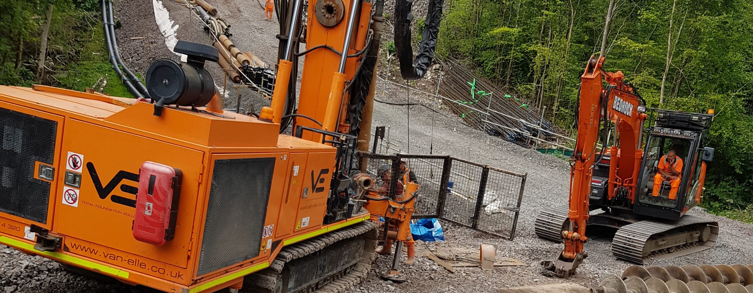
Sectional Flight Auger (SFA) Piling

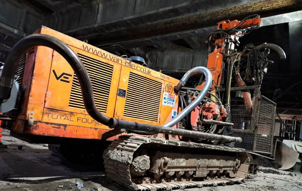
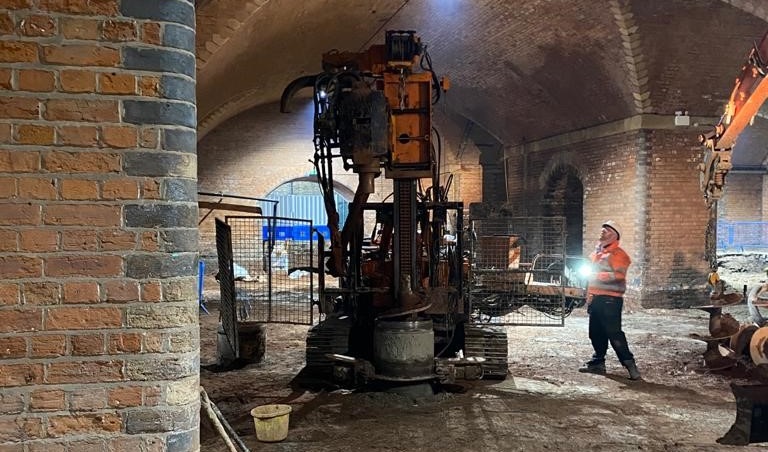
Sectional Flight Auger (SFA) piling enables the installation of piles in low-headroom environments or within restricted-access sites and are typically used in the same ground conditions as conventional continuous flight auger (CFA) piles. SFA piling is the preferred method where access is restricted or headroom is limited, and where CFA rigs are unable to operate.

As a bored, soil-replacement piling technique, it is particularly suitable for operations within buildings, beneath structures such as bridges, or in other areas with reduced headroom and limited access.We have the capability to construct piles up to 900 mm in diameter to significant depths, across a range of ground conditions throughout the UK. These piles can be installed with headroom constraints as low as 3.75 m.

SFA techniques include adding and removing augers to achieve design depth and can also include the use of temporary casing where ground conditions require.
Project Advantages

  • Specific, purpose-built rigs suited to restricted-access environments
  • Enables installation within buildings, beneath structures, or other low-headroom and logistically challenging sites
  • No requirement for bentonite or polymer support fluids, with temporary casing available where ground conditions require
  • Efficient, quiet and low-vibration technique, minimising disruption
  • Cost-effective and versatile, suitable across a wide range of ground conditions
  • Ideal for sensitive areas

Example Applications

  • Structural foundations
  • Sites with logistical or access constraints
  • Low-headroom environments, including within existing buildings and beneath structures
  • Contiguous and secant piled walls
  • Rail infrastructure and other sensitive environments
  • A wide range of ground conditions

Understanding SFA

The use of a specially developed fleet of rigs provides flexibility in both machine footprint and headroom capability, enabling installation in constrained environments.

SFA piles are constructed using sectional hollow-stem augers, which are bored into the ground. Additional auger sections are added progressively to achieve the required design depth.

Upon reaching the design toe level, concrete is pumped through the hollow stem as the auger is simultaneously withdrawn. Auger sections are removed in stages during withdrawal.

The reinforcement cage is then inserted into the fluid concrete, with the top of the reinforcement set in accordance with the design requirements.